Energy storage system block diagram

Schematic diagram of flywheel energy storage system simulation
Download scientific diagram | Schematic diagram of flywheel energy storage system simulation model. from publication: Control Strategy of DC Link Voltage Flywheel Energy Storage for Non Grid

Energy Storage System
Distributed energy systems: A review of classification, technologies, applications, and policies. Talha Bin Nadeem, Muhammad Asif, in Energy Strategy Reviews, 2023. 7.2.2 Energy storage. The concept of energy storage system is simply to establish an energy buffer that acts as a storage medium between the generation and load. The objective of energy storage systems

Energy Storage Systems: How to Easily and Safely
Figure 1 illustrates a typical BMS block diagram where the ESCU is highlighted in blue. While the ESCU is not optimized for functional safety applications, the user can implement protection circuits and/or redundancies

Pumped hydro storage block diagram. | Download Scientific Diagram
Download scientific diagram | Pumped hydro storage block diagram. from publication: An Overview on Energy Storage Options for Renewable Energy Systems | Developing technology to store electrical

The Primary Components of an Energy Storage System
Battery. The battery is the basic building block of an electrical energy storage system. The composition of the battery can be broken into different units as illustrated below. At the most basic level, an individual battery cell is an

Flywheel Energy Storage System | PPT | Free Download
Design of flywheel energy storage system Flywheel systems are best suited for peak output powers of 100 kW to 2 MW and for durations of 12 seconds to 60 seconds . The energy is present in the flywheel to provide higher power for a shorter duration, the peak output designed for 125 kw for 16 seconds stores enough energy to provide 2 MW for 1

a Single Line Diagram, b.Architecture of Battery Energy Storage System
Download scientific diagram | a Single Line Diagram, b.Architecture of Battery Energy Storage System from publication: Lifetime estimation of grid connected LiFePO4 battery energy storage systems

GRID CONNECTED PV SYSTEMS WITH BATTERY
A system designer will also determine the required cable sizes, isolation (switching) and protection requirements. Notes: 1. The new standard AS/NZS5139 introduces the terms "battery system" and "Battery Energy Storage System (BESS)". Traditionally the term "batteries" describe energy storage devices that produce dc power/energy.

Battery Management Systems (BMS)
the energy available. An example block diagram of a BMS is shown below which includes a microcontroller, sensors, both solid-state and electromechanical disconnects (switches), voltage regulators, communication interfaces, and protection circuits. Why is a Battery Management System (BMS) needed? Safety: Certain types of cell chemistries can

Battery Control Unit Reference Design for Energy Storage
Currently, a battery energy storage system (BESS) plays an important role in residential, commercial and 2.1 Block Diagram. Figure 2-1 shows the system diagram. ULN2803C AM2634 TPS62913RPUR TPS62913RPUR PHY DP83826E LMR51440 BQ79600 BQ79600 TPS4H160B TPS7A1601 TPS7B8133 RY_GND AC-DC Module TMDCNCD263

Block diagram of battery energy storage system performance model
Download scientific diagram | Block diagram of battery energy storage system performance model. from publication: Validating Performance Models for Hybrid Power Plant Control Assessment | The need

TECHNICAL BRIEF
With Enphase Energy System, homeowners have power when the grid goes down and can save money when the grid is up. Enphase Energy System includes a combination of the following Enphase products: IQ8™ Series Microinverters and Accessories: The Enphase Energy System is fully compatible with IQ 8

How Much Do You Know About Battery Management System Block Diagram
It provides a holistic view of the BMS architecture, aiding in troubleshooting, optimization, and ensuring the overall reliability of the energy storage system. Main Components of a BMS Block Diagram. The block diagram visually represents the key internal components and functionality of the BMS. It shows at a high level what''s inside the BMS.

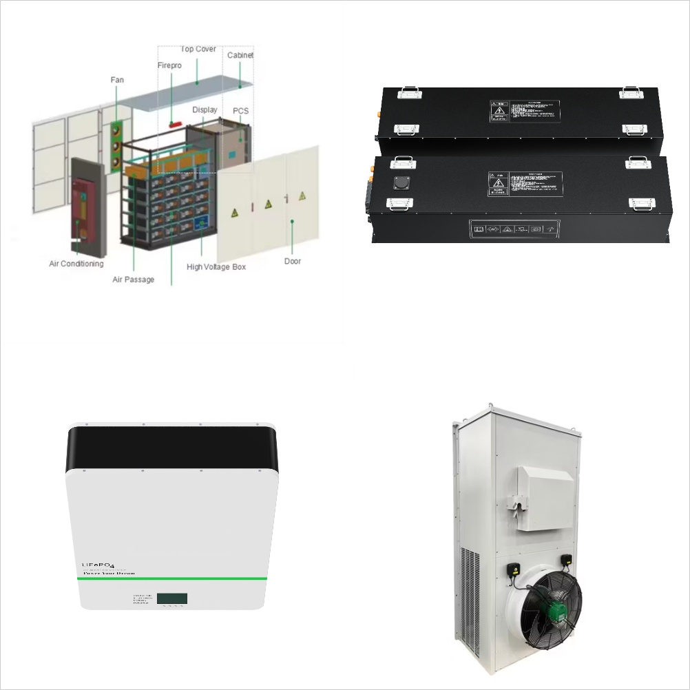
Energy Storage Systems
Energy Storage Systems are structured in two main parts. The power conversion system (PCS) handles AC/DC and DC/AC conversion, with energy flowing into the batteries to charge them or being converted from the battery storage into AC power and fed into the grid. Suitable power device solutions depend on the voltages supported and the power flowing.

Block Diagram Of Battery Management System (BMS)
Earlier limited to heavy and bulky lead-acid storage batteries, large-format batteries were used only where absolutely necessary as a means of energy storage. The above block diagram consists of the battery pack, battery

The Key Components of Battery Energy Storage Systems (BESS)
Battery Energy Storage Systems (BESS) play a fundamental role in energy management, providing solutions for renewable energy integration, grid stability, and peak demand management. In order to effectively run and get the most out of BESS, we must understand its key components and how they impact the system''s efficiency and reliability.

Battery energy storage systems (BESS) frequency regulation block diagram.
Download scientific diagram | Battery energy storage systems (BESS) frequency regulation block diagram. from publication: Voltage/Frequency Deviations Control via Distributed Battery Energy

Block diagram of the solar thermal energy storage system.
Download scientific diagram | Block diagram of the solar thermal energy storage system. from publication: Renewable Energy Integration: Economic Assessment of Solar Energy to Produce Biodiesel at

Appendix A
Appendix A- Energy Storage System Configuration Diagrams 2 . Appendix A- Energy Storage System Configuration Diagrams 3 . time for Energy Storage Systems, the functionalities need to be verified through extensive detailed review of the operating manuals and often inquiries with the

Battery Energy Storage System Modelling in DIgSILENT PowerFactory
The block diagram of the control structure is given in Fig. 7.5. The block diagram shows the components of the complete battery system (converter, battery, and measurement components), as well as the main control blocks (frequency droop, active and reactive power control, and charging and discharging control).
Energy Storage
Interactive Block Diagrams. Product Suggestions. Support Explore. power management, and energy conversion helps customers across the globe handle the challenges of Energy Storage Systems. We create suitable solutions for the evolution of the power grid. Interactive Block Diagram. 1 Select a diagram by solution.

Energy Storage: An Overview of PV+BESS, its Architecture,
Battery Energy Storage DC-DC Converter DC-DC Converter Solar Switchgear Power Conversion System Common DC connection Point of Interconnection SCADA ¾Battery energy storage can be connected to new and SOLAR + STORAGE CONNECTION DIAGRAM existing solar via DC coupling ¾Battery energy storage connects to DC-DC converter.

A Guide to Battery Energy Storage System Components
There are many different chemistries of batteries used in energy storage systems. Still, for this guide, we will focus on lithium-based systems, the most rapidly growing and widely deployed type representing over 90% of the market. In more detail, let''s look at the critical components of a battery energy storage system (BESS). Battery System

Related Contents
- Diagram flywheel energy storage
- Battery energy storage system control block
- Battery energy storage system single line diagram
- Solar energy block diagram with explanation Nepal
- Energy storage consumption of nmc versus lfp
- Orsted energy storage Malta
- Energy storage usvi
- Hydrogen energy storage canada
- Energy storage mos2
- Cryogenic energy storage system
- Nexamp energy storage
- Saint Helena high energy storage capacitor