Solar inverter battery charger circuit schematic

Solar Battery Charger Circuit Using Lm317 Voltage Regulator
Battery Charger Circuit Diagram With Auto Cut Off. Doc Solar Battery Charger Circuit Novaexamcell Eluru Academia Edu. Simple Nicd Battery Charger Eeweb. 12v Solar Inverter Battery Charger. Solar Charger Circuit Using Ic Lm317 Electronics Project. Circuit Diagram Of Lm317 It Is A Flexible Voltage Controller Ic Which Scientific. Solar Charger

2 Easy Automatic Inverter/Mains AC Changeover Circuits
2) 10KVA Solar-Grid Inverter Changeover Circuit with Low Battery Protection. In the second concept below I have explained how to build a 10kva solar grid inverter changeover circuit which also includes a low battery protection feature. The idea was requested by Mr. Chandan Parashar. Circuit Objectives and Requirements

Solar Charger Circuit Diagrams
How To Design Solar Nicad Battery Charger. Solar Charger Circuit With Boost Converter. Solar Charger Circuits Under Cell 7791 Next Gr. 12v 100ah Battery Charger Circuit Diy Electronics Projects. Circuit Diagram Of The Solar Battery Charger Scientific. 12v Solar Inverter Battery Charger.

Solar Inverter Battery Charger Circuit Diagram
The solar inverter battery charger circuit diagram outlined below is designed to help you understand how to construct and install a charger for your solar energy system. Before getting into the nitty-gritty of the circuit diagram

PV Solar Inverter Circuit Diagram
Circuit Diagram. Construction of Circuit. There are five stages of this Circuit: PV Solar panel. Battery Charger. Switching Pulse Oscillator. Switching Device. Step Up transformer. Solar Panel. This PV Solar Inverter

Calculating Solar Panel, Inverter, Battery Charger – Homemade Circuit
I have this item for solar system (1X200W mono panel,1X max solar input >50 12~24v 20Amp charging control unit,1X 2000W inverter,which type battery I need for 5 hours battery backup.and how many hours get it battery full

Simple Solar Battery Charger Circuit Diagram
12v Solar Inverter Battery Charger. Pwm Solar Battery Charger Circuit Homemade Projects. Lead Acid Battery Charger Circuit. Circuit Diagram Of The Solar Battery Charger Scientific. Simple Low Power Solar Battery Charging Circuit. How To Build A Solar Powered Battery Charger Circuit Basics. Circuit Zone Com Electronic Kits Projects Schematics

Hybrid Inverter Using Solar Battery Charger | PDF
WORKING PRINCIPLE OF HYBRID INVERTER – USING SOLAR BATTERY CHARGER Hybrid inverter using solar charger is combination of two circuits 1 arging circuit. 2 verter circuit 4.1 Charging Circuit When the solar panel''s output reaches 12 volts in the charging circuit, the battery is charged using solar energy.

800VA Pure Sine Wave Inverter''s Reference Design
2.3 Schematic of the Design Here H-bridge circuit converts battery DC voltage into AC using high frequency PWM (6 kHz to 20 KHz) thus feeding the 50-Hz transformer which Boost it to 120V/220V AC. The output of transformer contains a Furthermore the current that is flowing through the battery in Inverter mode and the Charging current

Hybrid Inverter Using Solar Battery Charger
USING SOLAR BATTERY CHARGER Hybrid inverter using solar charger is combination of two circuits and common contacts. So we are able to continuously charge 1 arging circuit. 2 verter circuit 4.1 Charging Circuit When the solar panel''s output reaches 12 volts in the charging circuit, the battery is charged using solar energy.

6V Solar Battery Charger Circuit
In the 6V solar battery charger circuit, the LM317 is set up to generate a fixed 7V output using the resistances 120 ohms and 560 ohms. Voltage Comparators and LED Indicators: How They Work: The voltage comparators in the LM324 quad op-amp are used to compare the voltage levels during the charging or discharging process of the battery.

Free Solar Inverter Circuit Diagrams
How To Design A Solar Inverter Circuit Homemade Projects. 24v To 12v 400w Dc Inverter. Pv Solar Inverter Circuit Diagram. Solar Panel Wind Vector Photo Free Trial Bigstock. How To Make A Simple Solar Inverter Circuit Homemade Projects. 100 Watt Inverter Circuit 12v To 220v Using Transistor. Grid Tie Solar Inverter Schematic. How To Make A

Solar Battery Charger Circuit with Transistor
The schematic shown here is a very efficient automatic solar-power based battery charger circuit. Which utilizes to charge 12V SLA batteries from solar-based cells. The circuit is utilizing an LM317T voltage controller IC.

Solar Battery Charger Circuit
Solar Battery Charger Circuit Diagram. Circuit Components. Solar panel – 17V; LM317 voltage regulator; DC battery; Diode – 1n4007; Capacitor – 0.1uF; please sir is this circuit the same as solar panel inverter control circuit? Reply. Prince says:

PV Solar Inverter Circuit diagram
Last Updated on March 16, 2024 . Inverter circuit gives Alternating Current (AC) output from battery Power source, but the battery requires constant DC supply to get charge, so the every inverter circuit contains Rectifier and battery charger segment. We need to provide AC input power to those circuits, then only we can get AC output from inverter circuit.

Simple Solar Ni-Cd Charger Circuit
12 Volt Solar Battery Charger Circuit; PV Solar Inverter Circuit; PV Solar Inverter Circuit Diagram; Automatic Solar Garden Light Using 555 Timer IC; Automatic Sequence Solar Battery Charger; 555 Timer Circuits 493; Alarm

Solar Hybrid Inverter Circuit Diagram
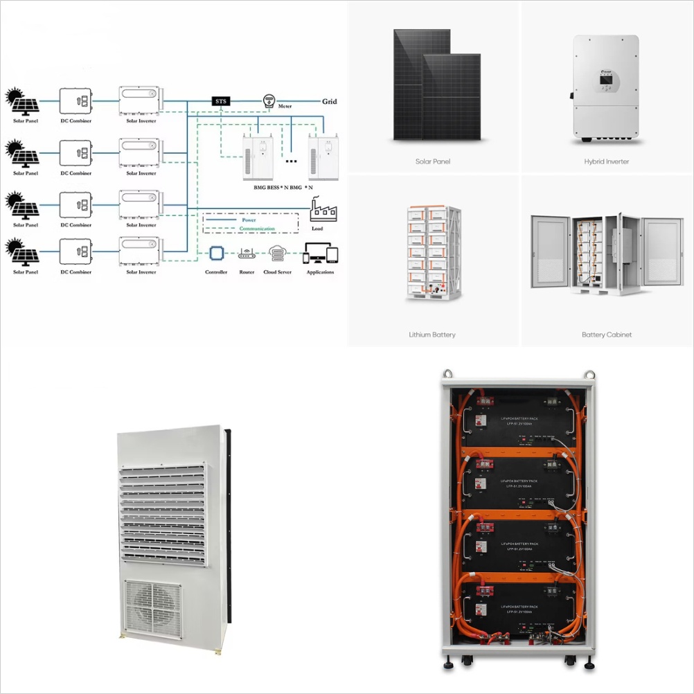
The solar hybrid inverter circuit diagram is split into four main components: the solar module, the solar combiner box, the solar control unit, and the solar battery. The solar module is responsible for capturing and storing the solar energy produced by the photovoltaic system, while the combiner box is used to connect multiple solar modules

Understanding the Wiring Diagram for Hybrid Solar Inverters: A
A hybrid solar inverter is a device that combines the functionality of a solar inverter and a battery charger. It is designed to convert the direct current (DC) power generated by solar panels into alternating current (AC) power, which can be used to power household appliances and

HYBRID INVERTER WITH SOLAR BATTERY CHARGING
Hybrid Inverter with Solar Battery Charging System consists of an inverter powered by a 12V Battery. This inverter generates up to 230V AC with the help of driver circuitry and a heavy load transformer. This battery gets charged from two sources, first being the mains power supply itself and second from the solar power.

Solar Inverter Circuit
Solar Inverter Circuit Without Battery 300 Watt Diy Electronics Projects. How Solar Power Works On Grid Off And Hybrid Systems Clean Energy Reviews. 12v Solar Inverter Battery Charger. How To Make Solar Inverter Circuit. At90s8535 Sg2524 Pwm Solar Panel Pv Inverter Circuit. Pv Solar Inverter Circuit Diagram. Off Grid Hybrid Bi Directional Solar

Hybrid Inverter With Solar Battery Charging Circuit Diagram
How To Design A Solar Inverter Circuit Homemade Projects. Battery Charger Power Inverters One Line Diagram Solar Inverter Photovoltaic System Png 689x534px Area. Ltc3652 Solar Battery Charger Lifepo4 Electronics Projects Circuits. Introducing Solis Hybrid Inverters Intelligent Energy Management Defining Green Life

Solar Panel Wiring Diagram for All Setups [+ PDFs] – Solartap
Solar panels; Inverter; Battery; Charger (or inverter/charger combo) Battery isolator; Battery monitor; Shunt; Busbar; Shore power plug; 12v switches and outlets; 3. Determine an Orientation. Solar panels and batteries can each be wired in one of two orientations: series or parallel. These orientations determine whether your devices

Schematic For Solar Battery Charger
A schematic for a solar battery charger consists of three main components: the solar panel, the charge controller, and the battery. The solar panel collects energy from the sun''s rays, the charge controller moderates the amount of energy collected, and the battery stores the energy for use when the sun''s energy is no longer sufficient.

3 Simple Solar Panel/Mains Changeover Circuits
Looking at the proposed circuit diagram, we see three basic stages, on the left an IC 741 circuit, at the center a voltage regulator stage using IC LM317, while on the top an AC/DC adapter circuit. and supplying a 24/7 power to the connected loads via the inverter output mains. Solar Battery Charger, AC/DC Adapter Changeover . The enclosed

MPPT Solar Charger with 3-Step Charger Circuit
For continuous operations, the MPPT solar charger circuit could consume approximately about 200mA. Over a 24-hour period this results to 4.8Ah or 60Wh each day from the 12V battery. This implies in case a 40W panel produces optimal power for 1.5 hours or higher every day, this could be adequate for any relevant load to operate.

6 FAQs about [Solar inverter battery charger circuit schematic]
What is a simple solar charger circuit?
Simple solar charger circuits are small devices which allow you to charge a battery quickly and cheaply, through solar panels. A simple solar charger circuit must have 3 basic features built-in: It should be low cost. Layman friendly, and easy to build. Must be efficient enough to satisfy the fundamental battery charging needs.
What is an energy saving Solar inverter battery charger?
Here is an energy saving solar inverter battery charger. It harvests solar energy to replenish 12 volt inverter battery. It has auto cut off facility to stop charging when the battery attains full charge. The charger uses a 24 volt solar panel as input.
How does a solar inverter work?
The output voltage from the solar panel is immediately supplied into the LM317 positive regulator circuit, which is regulated to produce 12 volts. The battery is wired to this bias by a Schottky diode. The CD4047IC integrated Circuit is connected and set up as an astable multivibrator in this solar inverter circuit.
How does a 12 volt inverter battery charger work?
It harvests solar energy to replenish 12 volt inverter battery. It has auto cut off facility to stop charging when the battery attains full charge. The charger uses a 24 volt solar panel as input. The circuit uses a variable voltage regulator IC LM 317 to set the output voltage steady around 16 volts.
How to charge a battery with a solar panel?
But to charge a battery with a solar panel, the most popular choice is the MPPT or maximum power point tracker topology because it provides much better accuracy than other methods like PWM controlled chargers. MPPT is an algorithm commonly used in solar chargers.
How does a solar panel Charger work?
The charger uses a 24 volt solar panel as input. The circuit uses a variable voltage regulator IC LM 317 to set the output voltage steady around 16 volts. Variable resistor VR controls the output voltage. When the solar panel generates current, D1 forward biases and Regulator IC gets input current.
Related Contents
- Advantages of solar inverter battery charger
- Ac solar battery charger and inverter
- Solar panels inverter and battery Tajikistan
- Solar inverter with inbuilt battery Jamaica
- Turks and Caicos Islands solar micro inverter battery backup
- 100w solar inverter circuit diagram
- Micronesia direct solar inverter without battery
- Ireland best battery for solar inverter
- Mozambique inverter battery for solar panels
- Tata solar panel with inverter and battery price
- Aa solar battery charger to usb power bank diy
- Solar panel with battery charger